Tangram draws map features using its built-in draw styles: polygons, lines, points, text, and raster. Using the styles element, you can customize the behavior of these draw styles, either by using the many built-in customization features, or by making your own effects from scratch using shaders.
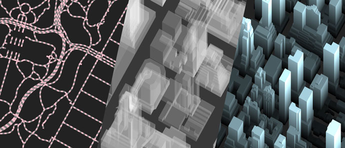
This tutorial will explore three things you can make with custom styles: dashed lines, transparent polygons, and shader effects.
Note: in the examples in this tutorial, we are relying on the layer name shortcut and style name shortcut.
Dashed Lines
Let's use one of the built-in style customization options, dash, to draw some dashed lines.
(To follow along, use Tangram Play, a custom Tangram setup, or follow the links to the examples throughout this tutorial.)
Add a datasource to your map with a sources entry, then add some lines to your map - in our example, we'll start with road features from the Mapzen Vector Tile Service.
sources:
    nextzen:
        type: TopoJSON
        url: https://tile.nextzen.org/tilezen/vector/v1/all/{z}/{x}/{y}.topojson

layers:
    roads:
        data: { source: nextzen }
        draw:
            lines:
                order: 1
                width: 5px
                color: gray

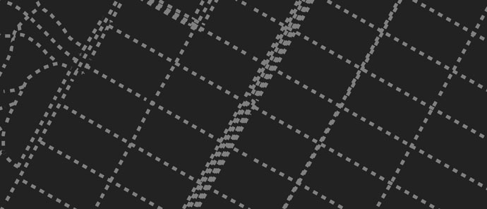
Now make a custom draw style called "_dashes" – this name could be anything, and the leading underscore isn't required, but it's a handy way to remember which things we named ourselves.
Give the new style a base draw style of "lines", then add a dash parameter. The dash parameter takes an array, which sets the length of the dashes and gaps.
styles:
    _dashes:
        base: lines
        dash: [1, 1]
The values of the dash parameter are relative to the width of the line – a value of 2 produces a dash or gap twice as long as the line's width, .5 is half the line's width, and 1 produces a square.
So far our new style isn't used anywhere, so no dashes will be seen. To fix this, rename the draw group of the "roads" layer from lines to _dashes, and the roads will be drawn in the custom style.
sources:
    nextzen:
        type: TopoJSON
        url: https://tile.nextzen.org/tilezen/vector/v1/all/{z}/{x}/{y}.topojson

styles:
    _dashes:
        base: lines
        dash: [1, 1]

layers:
    roads:
        data: { source: nextzen }
        draw:
            _dashes:
                order: 1
                width: 5px
                color: gray
 ( Try different values for dash and width in Play ▶ )
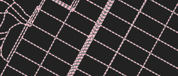
By default, the dash style has a transparent background, but you can give the background a solid color using the dash_background_color option:
styles:
    _dashes:
        base: lines
        dash: [1, 1]
        dash_background_color: pink
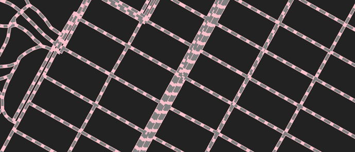
You can also apply an outline:
layers:
    roads:
        data: { source: nextzen }
        draw:
            _dashes:
                order: 1
                width: 5px
                color: gray
                outline:
                    color: pink
                    width: 1px
Transparency with Blend Modes
Now let's add transparency to a polygons layer, using another custom styling option, blend.
The blend modes are not true 3D transparency, but function like the blend modes in Photoshop, which work by compositing layered pixels together.
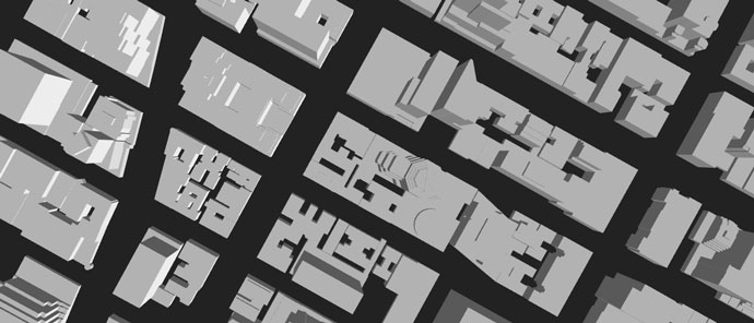
Start with a buildings data layer drawn with a basic polygons style:
sources:
    nextzen:
        type: TopoJSON
        url: https://tile.nextzen.org/tilezen/vector/v1/all/{z}/{x}/{y}.topojson

layers:
    buildings:
        data: { source: nextzen }
        draw:
            polygons:
                order: 1
                color: [.7, .7, .7]
                extrude: true
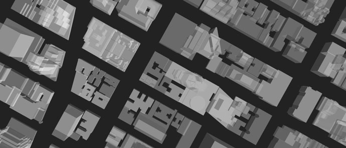
Add a new style based on the polygons style – ours is named "_transparent". Then, add a blend mode of overlay, and set the buildings draw style to match the name of the custom style.
There's one more step which is easy to overlook: right now the building layer's color value is a solid gray, [.7, .7, .7]. The three values in that array are the Red, Green, and Blue channels. But there's another possible channel for Alpha, which controls transparency, and if you don't specify it, it defaults to 1, which is opaque.
The blend modes respect alpha, so let's add an alpha value of .5, which is 50% opacity, and we will achieve transparency at last:
sources:
    nextzen:
        type: TopoJSON
        url: https://tile.nextzen.org/tilezen/vector/v1/all/{z}/{x}/{y}.topojson

styles:
    _transparent:
        base: polygons
        blend: overlay

layers:
    buildings:
        data: { source: nextzen }
        draw:
            _transparent:
                order: 1
                color: [.7, .7, .7, .5]
                extrude: true
 ( Experiment with different RGB and alpha values in Play ▶ )
(Check out Tangram's color documentation to see how color values may be specified.)
Shader Effects
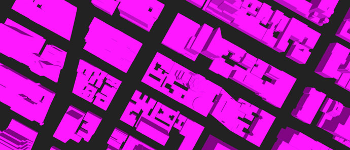
Custom shaders are also achieved through custom styles, using the shaders block. Starting with the buildings layer again, add a new entry to the styles block named "_custom", and change the draw style of the buildings layer to match.
Then, add a shaders block to the style, with a blocks block and a color block inside that. This color block will hold the shader code, which is written in GLSL. To start off (and to tell it's working) set the output color to something like vec3(1, 0, 1) which is GLSL's way of specifying the RGB values for magenta:
sources:
    nextzen:
        type: TopoJSON
        url: https://tile.nextzen.org/tilezen/vector/v1/all/{z}/{x}/{y}.topojson

styles:
    _custom:
        base: polygons
        shaders:
            blocks:
                color: |
                    color.rgb = vec3(1, 0, 1);

layers:
    buildings:
        data: { source: nextzen }
        draw:
            _custom:
                order: 1
                extrude: true
(You'll notice shading on the sides of buildings – this is because of the default light settings. Read more about these in our lighting documentation.)
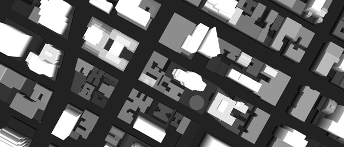
Now you can write your own shader functions to control the color of the buildings directly. You can also use built-in variables if you wish to control the color with properties of the geometry or scene. Let's get the worldPosition() of each vertex and reference that in the shader's color block, so the buildings will be colored based on z-value (aka height):
styles:
    _custom:
        base: polygons
        shaders:
            blocks:
                color: |
                    color.rgb *= vec3(worldPosition().z) / 100.;
And when animated: true is added to the style, you can make effects based on the u_time internal variable:
styles:
    _custom:
        base: polygons
        animated: true
        shaders:
            blocks:
                color: |
                    color.rgb *= worldPosition().zzz / 100.;
                    color *= sin(u_time);

Experiment with different color values to see the way the shader's color and the draw layer's color interact.
For more about internal variables available in shaders, see Built-ins, defaults, and presets.
Questions? Comments? Drop us a line on GitHub, on Twitter, or via email.