Projections Overview
Tangram is optimized for standard Web Mercator tiles. However, through the clever use of vertex shaders, the apparent position of vector data may be modified, effectively "reprojecting" the data on the fly.
Shaders are created as part of a custom style. The style used to create the above effect looks like this:
styles:
    warp:
        animated: true
        base: lines
        shaders:
            defines:
                EARTH_RADIUS: 6378137.0 //radius of ellipsoid, WGS84
            blocks:
                position: |
                    position.y += sin(u_time + position.x/EARTH_RADIUS * 2.) * EARTH_RADIUS * .5;
The whole scene file is only 26 lines long, and can be found here.
The general idea for any Tangram projection is the same: use a custom style with a vertex shader in it, to modify the position of the geometry generated from the source data.
Making a new Tangram projection
Some fine print
Most map projections work with spherical "geodetic" coordinates, aka latitude and longitude, typically represented by phi (ϕ) and lambda (λ) respectively. Many tilesets, including Nextzen's vector tiles, encode data in this format. However, by the time this data gets to Tangram's vertex shader, it's been converted to screenspace coordinates, measured in "Mercator meters." These strange units equal standard meters at the equator but represent increasingly smaller distances the further you get from the equator, because Mercator.
This isn't a problem if you don't mind distorting the projected data directly, as the "wavy" shader above does, but to make it work with other standard projections, you must first "unproject" the data data back to spherical coordinates.
Convert to geodetic coordinates
Tangram vertex coordinates are measured from the center of the viewport. To convert a vertex position to latitude and longitude, we must also refer to a built-in uniform called "u_map_position", which stores the center of the viewport in Mercator meters from the top-left corner of the Web Mercator base tile, which is 180 W, 85.05 N.
To convert Tangram's Mercator coordinates to standard geodetic coordinates, two separate functions are needed:
float EARTH_RADIUS = 6378137.0 //radius of ellipsoid, WGS84
float y2lat_m (float y) { return 2.0*atan(exp((y/EARTH_RADIUS)))-HALF_PI; }
float x2lon_m (float x) { return x/EARTH_RADIUS; }
Pass the Mercator meters coordinates to these functions to get latitude and longitude:
// u_map_position = center of screen
// position.xy = vertex screen position in meters from the center of the screen
vec2 mercator = u_map_position.xy + position.xy;
float lat = y2lat_m(mercator.y);
float lon = x2lon_m(mercator.x);
Reproject to taste
Once you have lat & lon, you can re-transform them any way you like.
Here's a basic stereographic (aka "spherical") projection:
// convert from lat, lon to position on a sphere
vec3 latLongToVector3(float lat, float lon, float radius) {
    float phi = lat;
    float theta = lon;

    float x = radius * cos(phi) * cos(theta);
    float y = radius * cos(phi) * sin(theta);
    float z = radius * sin(phi);
    return vec3(x,z,y);
}
If you use this in a vector shader, it looks like this:
position.xyz = latLongToVector3(lat, lon, 2.) * EARTH_RADIUS;
Interaction Example: Globe
Projections may sometimes be adjustable through the use of special variables to become interactive – for instance, to center on a specific point on the globe – but not all projection algorithms include those sorts of variables. In the above example, the projection draws a globe centered on the equator, with [0,0] on the right and north up. As it stands there is no accomodation for other views.
We could add some variables to the projection function to make it interactive, but in this case it's simpler to modify the result with some extra steps:
// rotation matrix transformations
mat3 rotateX3D(float phi){
    return mat3(
        vec3(1.,0.,0.),
        vec3(0.,cos(phi),-sin(phi)),
        vec3(0.,sin(phi),cos(phi))
    );
}
mat3 rotateY3D(float theta){
    return mat3(
        vec3(cos(theta),0.,-sin(theta)),
        vec3(0.,1.,0.),
        vec3(sin(theta),0.,cos(theta))
    );
}

// Latitude_Of_Origin
float centerlat = y2lat_m(u_map_position.y);
// Central_Meridian
float centerlon = x2lon_m(u_map_position.x);

// rotate globe with map navigation
// 90 degrees in radians = 1.5708
position.xyz *= rotateY3D((-centerlon - 1.5708));
position.xyz *= rotateX3D(-(centerlat));
Now the globe will be centered on the map's location, and will respond to navigation.
- Interactive demo: http://meetar.github.io/projection-tests/?globe.yaml
- Full scene file: globe.yaml
- Repo: https://github.com/meetar/projection-tests/
Interaction Example: Albers
For comparison, the Albers conic projection explicitly includes the concept of a center point plus two "standard parallels" – these function as variables which change the result.
// convert from lat/long to albers -- from https://gist.github.com/RandomEtc/476238
vec2 albers(float lat, float lng, float lat0, float lng0, float phi1, float phi2) {
    float n = 0.5 * (sin(phi1) + sin(phi2));
    float c = cos(phi1);
    float C = c*c + 2.*n*sin(phi1);
    float p0 = sqrt(C - 2.*n*sin(lat0)) / n;
    float theta = n * (lng * PI/180. - lng0);
    float p = sqrt(C - 2.*n*sin(lat* PI/180.)) / n;

    float x = p * sin(theta);
    float y = p0 - p * cos(theta);

    return vec2(x,y);
}
The Albers implementation below takes the viewport's center as the center of the projection, and arbitrarily uses latitudes +/- 10 degrees as the standard parallels, because I thought they looked nice. A couple of helper functions are used to convert values to the range expected by the projection: one to convert from meters to degrees, and another to convert to radians. (The radians requirement isn't explicit in the projection, but it's quite common, because trigonometry is built around radians.) (In fact this would all be a lot easier if latitude and longitude were in radians to begin with. I'll notify the Babylonians.)
position: |
    // mercator position of the current vertex, u_map_position = center of screen,
    // position.xy = vertex screen position in meters from the center of the screen
    vec2 mercator = u_map_position.xy + position.xy;
    float lat = y2lat_m(mercator.y);
    float lon = x2lon_m(mercator.x);

    // Latitude_Of_Origin
    float centerlat = deg2rad(y2lat_m(u_map_position.y));
    // Central_Meridian
    float centerlon = deg2rad(x2lon_m(u_map_position.x));

    // Standard_Parallel_1
    float phi1 = deg2rad(y2lat_m(u_map_position.y) + 10.);
    // Standard_Parallel_2
    float phi2 = deg2rad(y2lat_m(u_map_position.y) - 10.);

    position.xy = albers(lat, lon, centerlat, centerlon, phi1, phi2)*EARTH_RADIUS;
- Interactive demo: http://meetar.github.io/albers/
- Full scene file: scene.yaml
- Repo: https://github.com/meetar/albers/
Limitations
There are some limitations to these techniques – as they all take place entirely in the vertex shader, Tangram doesn't "know" about them, and continues to fetch, build, and draw tiles as though they were still in standard Web Mercator.
Tiles
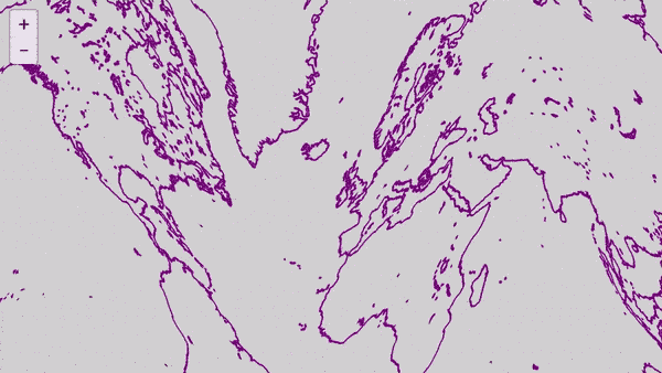
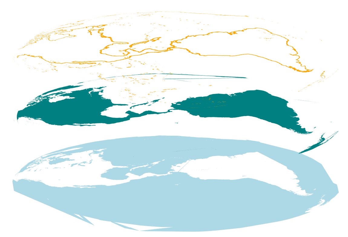
For instance, tiles will continue to be fetched for the current Web Mercator viewport, which means if your projection expands the effective view, tiles may appear to be missing or duplicated. In the example below, tiles to the north are missing, because Tangram doesn't realize they are needed:
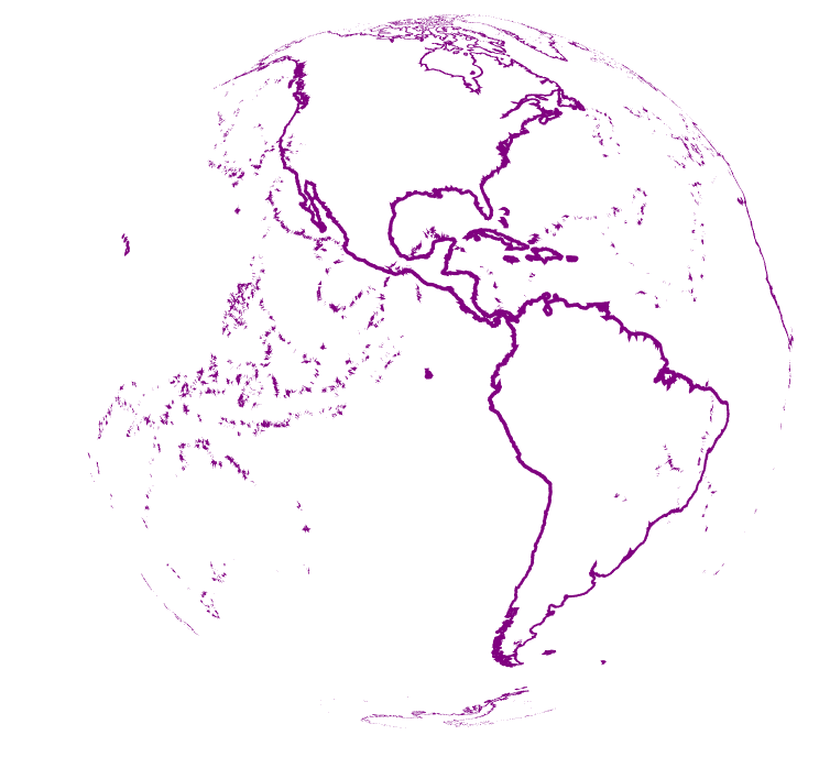
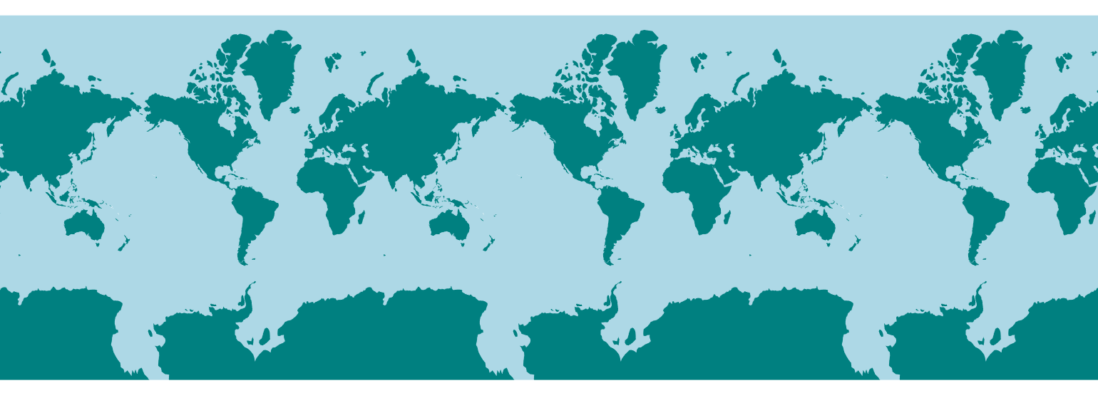
And in the globe example, at low zooms the earth is being drawn multiple times, which is obvious in standard Web Mercator:
But not in the globe, because the repeated tiles are wrapped around and layered on top of each other. This can cause surprises if you are using any kind of transparency. There may be ways to "clip" the projection to only draw the front-facing hemisphere, but they may not work precisely as expected, due to the Hinges issue mentioned below.
Here's code which prevents this kind of looping, by simply moving any vertices which are half a globe away from the center of the map back to the allowed limit:
shaders:
    defines:
        EARTH_RADIUS: 6378137.0 //radius of ellipsoid, WGS84
        HALF_CIRC: 20037508.5 //half-circumference of earth
    blocks:
        position:
            // handle low-zoom longitude-repetition
            if (position.x > HALF_CIRC) position.x = HALF_CIRC;
            if (position.x < -HALF_CIRC) position.x = -HALF_CIRC;
This technique is used in the "globe warp" example.
Layers
Projections may appear to be drawn in 3D, but invidual layers are still being ordered in 2D space as specified in the scene file. For instance, in a globe projection, if you set a the order of a line layer above that of a polygon layer, that ordering will be in screenspace, not relative to the surface of the Earth. In this case, lines on the back side of the globe may be drawn over water features in the front of the globe.
This is because of the way Tangram's order system is optimized for 2D cartography, allowing layers to be rearranged and composited without requiring more complex 3D operations. Unfortunately this means more complex 3D operations aren't possible in the way they might be in a classical 3D application.
Hinges
Maps are drawn with lines, but vertex shaders can only change the position of vertices. If your projection wants to curve the map, and there are not enough vertices in your geometry to draw curved lines, you will get straight lines drawn directly between the available vertices instead.
This effect may be exacerbated by the fact that numerous optimization steps in the Tangram pipeline deliberately remove apparently "extraneous" detail, such as colinear vertices. These steps are fine for a Web Mercator map, but may produce unexpected results in other situations.
In the example below, the projection is attempting to "bend" various large flat polygons backward in 3D space, but there aren't enough vertices in the sparse ocean geometry to produce smooth curves – so they wind up just going straight back to the next available polygon edge.

This limitation may also be seen when "clipping" a projection – there's currently no way to slice a polygon at an arbitrary point without adding vertices. Maybe someday.
Iterations
Many projections (such as the Mollweide) include some kind of iterated step, intended to converge toward an ideal solution, which will theoretically be reached only if the iteration is performed an infinite number of times. In practice most people don't have that kind of patience, so the iterated step is performed until some kind of threshold is achieved.
Unfortunately, vertex shaders don't allow this kind of non-deterministic loop. As part of the tradeoff for extremely fast execution, shaders must know beforehand exactly what code they'll be running. Loops are allowed only if they have a fixed number of iterations. So instead of testing for some kind of condition, just pick a number of loops that's good enough for your purposes. The result won't be as accurate in some cases, and less efficient in others, but it should mostly work out fine. This one from the Mollweide is being run 4 times, because it looks better than when it was run 3 times, and 5 times didn't look much different:
// convert from lat/lon to mollweide -- Adapted from https://github.com/d3/d3-geo-projection/blob/master/src/mollweide.js
float mollweideBromleyTheta(float phi) {
    float cpsinPhi = PI * sin(phi);
    for ( int i = 4; i != 0; i--) {
        float delta = (phi + sin(phi) - cpsinPhi) / (1. + cos(phi));
        phi -= delta;
    }
    return phi / 2.;
}
Adding a Projection to a Style
The simplest way to integrate a projection with an existing style is to mix it in. Here's a sample structure:
### my-projection.md

# define your projection here
styles:
    my-projection-style:
        shaders:
            blocks:
                # you might have some helper globals
                globals:
                # projection code goes in the "position" block
                position: |
### existing-style.md

# import the projection here
import: my-projection.md

styles:
    existing-style:
        base: polygon
        # mix the projection in here
        mix: my-projection-style

layers:
    earth:
        existing-style: # this style will now use your custom projection
If you don't have any custom styles in your scene (or if you have lots of custom styles in your scene file), it might be useful to set up some custom base styles, like so:
styles:
    projected-polygons:
        base: polygons
        mix: my-projection
    projected-lines:
        base: lines
        mix: my-projection
Then you can replace any instance of plain polygons or lines in your draw layers with the projected versions. If you have lots of custom styles, this trick allows you to do the mixes just once, instead of per style.